SphereWalker
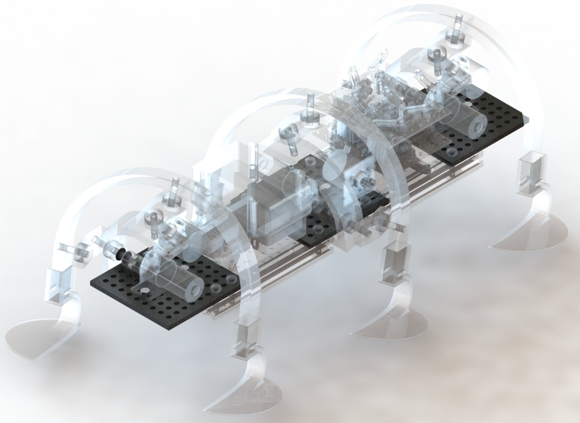
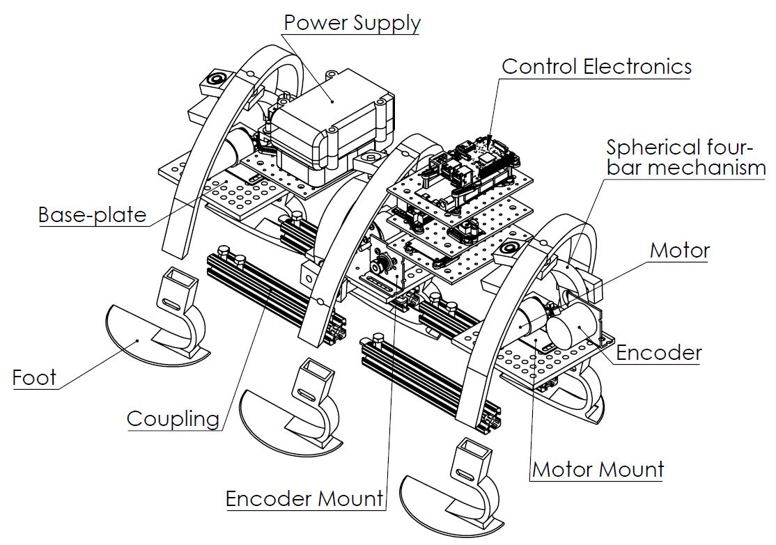
A NASA-funded research project exploring a hexapod that walks stably using only 3 motors. SphereWalker’s motion is based on a spherical four-bar mechanism, designed to carry payloads on lunar terrain while operating autonomously or via remote control.
Mission statement
Why SphereWalker exists
The SphereWalker project’s goal is to create a hexapod that can walk six legs using only three motors. It is designed to support and carry loads on the surface of the moon and operate autonomously or via remote control. The design emphasizes efficiency, stability, and robust motion over varied terrain.
Origin: spherical four-bar mechanism
Where the motion comes from
SphereWalker’s motion is based on a spherical four-bar mechanism. A single motor drives a spherical motion through the rotation of one link, producing a repeatable path. The mechanism is implemented with feet on the coupler link to propel the robot forward.
Advancements and iteration
From rigid joints to controlled turning
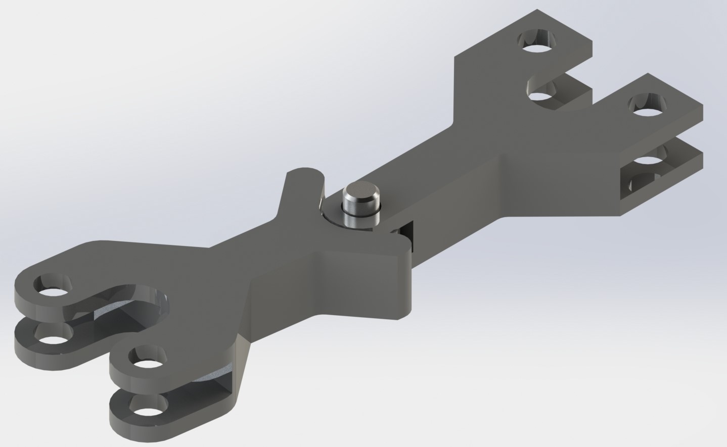
This Earlier versions used rigid joints and spiked feet. A key improvement was designing and implementing hinged joints. Those joints enabled controlled turning via coded step sequences, and also supported a more stable electronics “brain stem” mounting approach as the system evolved.
Walking gaits and turning
Sequenced half-rotations
Turning is achieved by sequencing half-rotations of the legs. From the home position, one half-rotation of the front leg, followed by a half-rotation of all three legs, then another half-rotation of the front leg, and finally a half-rotation of all three legs produces a right turn and returns the legs toward the home pose due to the spherical motion. To turn left, an additional half-rotation of all three legs can be added at the beginning and end to return cleanly to the home position.
Foot design evolution
Traction, damping, and soft terrain performance
Foot Design 1
The original approach used stiff rubber balls with spikes for traction, but performance was limited outside dirt. A wider curved design improved mounting and contact area and better matched the spherical step path, but still struggled with impact damping and sinking in granular terrain. Foam pellets and an outer tread layer improved shock reduction and traction, but sinking and motion were still not ideal.
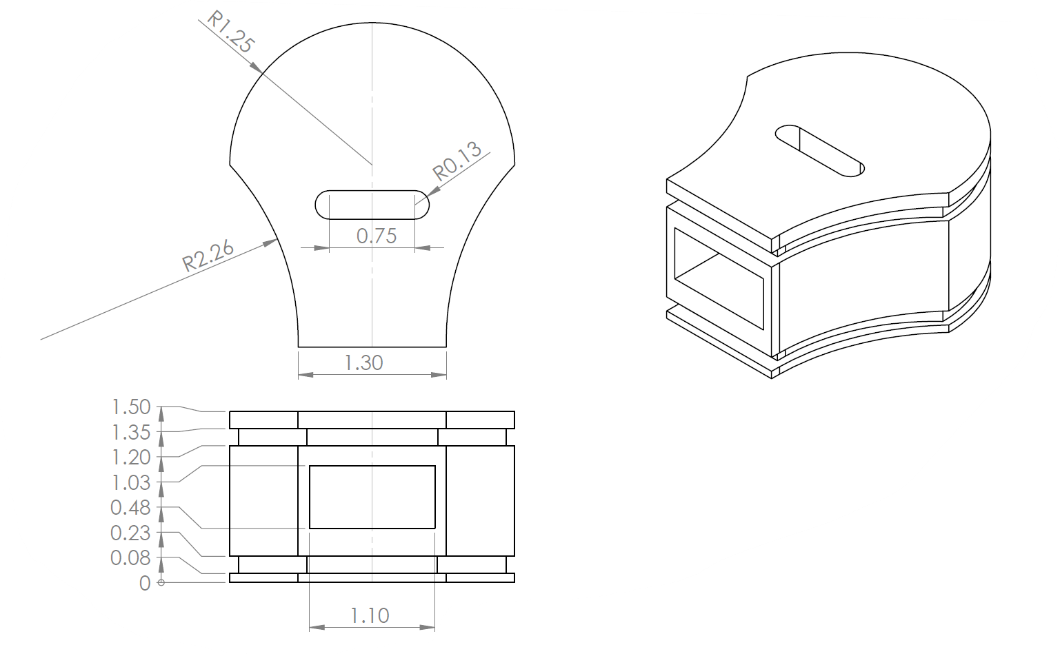
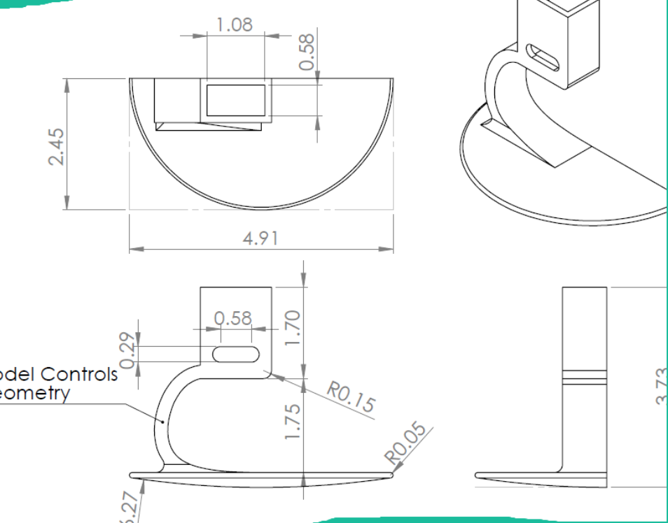
Final Foot Design
The final design was modeled after a prosthetic leg. The geometry adds natural damping through controlled flexion, increases surface area to reduce sinking, and follows the spherical motion closely for cleaner ground contact. A textured bottom improves traction across varied surfaces.
Modeled for ROS
Simulation + integration workflow
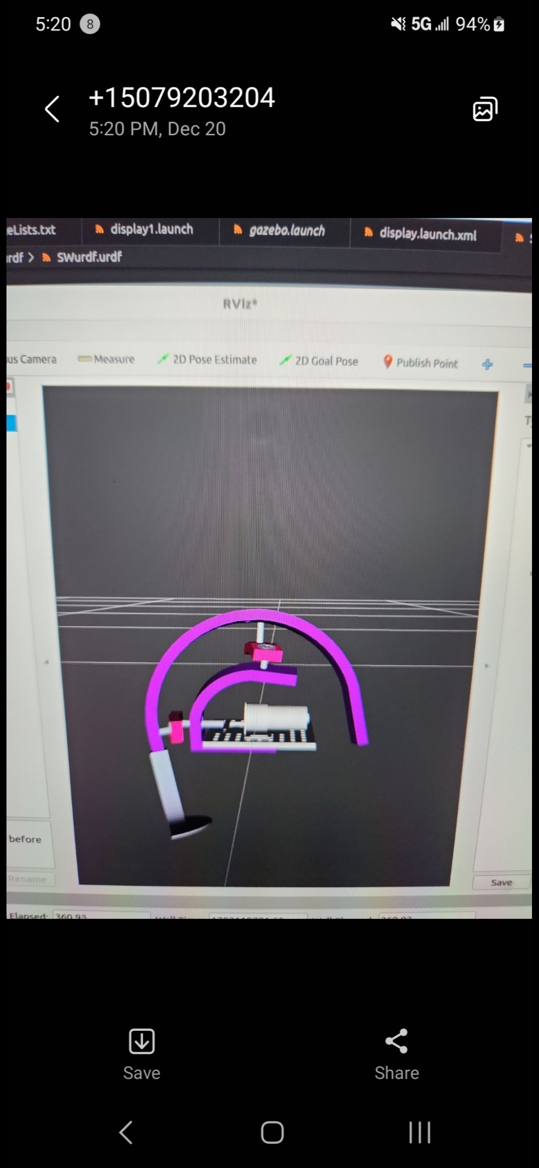
A later step was modeling SphereWalker in ROS to support a full robotics simulation and controls. It allowed for easier communication, validation and more uniform behavior with standard robotics tooling.
Video demo
Before final feet were attached